BMP Signaling
Spatio-temporal model of BMP signaling
Introduction
Juxtaposed sources of bone morphogenetic protein (BMP) and Nodal signaling molecules induce the formation of a full body axis in zebrafish embryos. Soh et al. studied body axis formation in zebrafish by transplanting signaling sources, specifically single clones expressing mouse BMP4 (mBMP4), and thereby inducing a secondary axis. mBMP4 diffuses and forms a morphogen gradient in the host tissue where differential signal transduction kinetics for pSmad2 versus pSmad5 lead to narrow (pSmad2) versus wide (pSmad5) signal activity ranges in response to the same morphogen gradient (mBMP4) as input.
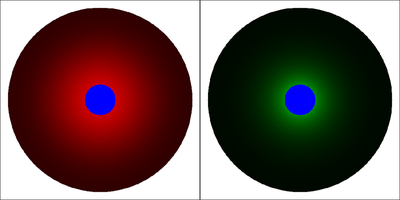
Soh et al. used mathematical modeling and simulation in COMSOL to explore the signal activity ranges in the mBMP4-pSmad2-pSmad5 system. The below Morpheus model implements the same partial differential equations (PDEs) and parameter values as published in Suppl. Section “Mathematical modeling” of the referenced paper. This simulation reproduces Fig. 3B of the referenced paper.
Description
- Units are
- A radial coordinate
Analysis). - Also optionally, time courses of mean concentrations over the domain can be plotted (temporarily inactivated in the model file, section
Analysis). - Note, the resulting state at
- Note, the Morpheus model uses
- The color scales for the two displayed fields are chosen such that red corresponds to maximum pSmad5 of
 ([Figure 3B](https://www.cell.com/cell-reports/fulltext/S2211-1247(20)30365-X?_returnURL=https%3A%2F%2Flinkinghub.elsevier.com%2Fretrieve%2Fpii%2FS221112472030365X%3Fshowall%3Dtrue#fig3)). [*CC BY-NC-ND 4.0*](https://creativecommons.org/licenses/by-nc-nd/4.0/legalcode)](/media/model/m2982/Soh2020_Fig3B_hu4589d47a6e43d6f6c84b0d3b3d770d42_210020_b6d67cfd89a69ef65ee4a6d312f68b84.png)

Reference
This model is described in the peer-reviewed publication:
G. H. Soh, A. P. Pomreinke, P. Müller: Integration of Nodal and BMP Signaling by Mutual Signaling Effector Antagonism. Cell Rep. 31 (1): 107487, 2020.
Model
BMP_signaling.xml
XML Preview
<?xml version='1.0' encoding='UTF-8'?>
<MorpheusModel version="4">
<Description>
<Details>Full Title: Spatio-temporal BMP signaling model
This simulation reproduces Fig. 3B of the referenced paper. Parameter values are as published in Suppl. Section "Mathematical modeling" except for the size of the mBMP expressing clone, see Note 1 below. The results illustrate that different signal transduction kinetics can determine specific activity ranges of pSmad5 and pSmad2 in response to the same gradient of mBMP4, the latter being established by a localized source and diffusion, decay in a 2D domain.
A radial coordinate "x" is used to optionally plot the concentration profiles. Also optionally, time courses of mean concentrations over the domain can be plotted. Both plotting options are included but temporarily inactivated in the model file.
Reference: The model is described in the peer-reviewed publication "Integration of Nodal and BMP Signaling by Mutual Signaling Effector Antagonism" by Gary Huiming Soh, Autumn Penecilla Pomreinke, Patrick Müller. Cell Reports 31, 107487, 2020, https://doi.org/10.1016/j.celrep.2020.03.051
Author of Morpheus model: peter.brusch.dd@gmail.com
Date of Morpheus model: November 21, 2020
Software: Morpheus (open-source), download from https://morpheus.gitlab.io
Units are: [space]=micrometer, [time]=second
Note: 1. This Morpheus model uses r=50 (micrometers) for the radius of the (blue) source region in the center of the (black) simulation domain with radius 300 micrometers. This corresponds to the geometry used in Fig. 3B of the referenced paper.
2. The resulting state at 7200sec is a transient state as the mBMP4 field is initialized as zero, a steady state with higher concentration values is approached at ten times longer duration.
3. The color scales for the two displayed fields are chosen such that red corresponds to maximum pSmad5 of 5000 and green to maximum pSmad2 of 5.
</Details>
<Title>BMP signaling</Title>
</Description>
<Space>
<Lattice class="square">
<Neighborhood>
<Order>1</Order>
</Neighborhood>
<Size symbol="size" value="650, 650, 0"/>
<NodeLength symbol="dx" value="1"/>
<BoundaryConditions>
<Condition type="noflux" boundary="x"/>
<Condition type="noflux" boundary="-x"/>
<Condition type="noflux" boundary="y"/>
<Condition type="noflux" boundary="-y"/>
</BoundaryConditions>
<Domain boundary-type="noflux">
<Circle diameter="600"/>
</Domain>
</Lattice>
<SpaceSymbol symbol="s" name="Position"/>
</Space>
<Time>
<StartTime value="0"/>
<StopTime symbol="StopTime_in_seconds" value="7200"/>
<TimeSymbol symbol="Time" name="Time in seconds"/>
</Time>
<Global>
<Constant symbol="r" name="Radius of mBMP4 expressing clone in micrometer" value="50"/>
<Field symbol="domain" value="1"/>
<Field symbol="clone" name="Area of mBMP4 clone" value="if((s.x-0.5*size.x)^2+(s.y-0.5*size.y)^2<=r^2, 1, 0)"/>
<Field symbol="mBMP4" name="mouse BMP4 protein concentration" value="0">
<Diffusion rate="3"/>
</Field>
<Field symbol="pSmad5" value="0"/>
<Field symbol="pSmad2" value="0"/>
<System time-step="1" solver="Runge-Kutta [fixed, O(4)]">
<DiffEqn symbol-ref="mBMP4" name="Marker reaction-diffusion model">
<Expression>k1*clone-k2*mBMP4</Expression>
</DiffEqn>
<DiffEqn symbol-ref="pSmad5">
<Expression>k5*mBMP4/(kd+mBMP4) - k3*pSmad5</Expression>
</DiffEqn>
<DiffEqn symbol-ref="pSmad2">
<Expression>k6*mBMP4/(ke+mBMP4) - k4*pSmad2</Expression>
</DiffEqn>
<Constant symbol="k1" value="1"/>
<Constant symbol="k2" value="1E-4"/>
<Constant symbol="k3" value="1E-4"/>
<Constant symbol="k4" value="1E-4"/>
<Constant symbol="k5" value="1"/>
<Constant symbol="k6" value="1"/>
<Constant symbol="kd" value="100"/>
<Constant symbol="ke" value="1E6"/>
</System>
<Function symbol="mBMP4_observable">
<Expression>(1+mBMP4)*(1-clone)*domain - clone</Expression>
</Function>
<Function symbol="pSmad5_observable">
<Expression>(1+pSmad5)*(1-clone)*domain - clone</Expression>
</Function>
<Function symbol="pSmad2_observable">
<Expression>(1+pSmad2)*(1-clone)*domain - clone</Expression>
</Function>
<Function symbol="x">
<Expression>s.x-size.x/2</Expression>
</Function>
<Variable symbol="mean_mBMP4" value="0.0"/>
<Variable symbol="mean_pSmad5" value="0.0"/>
<Variable symbol="mean_pSmad2" value="0.0"/>
<Mapper time-step="100">
<Input value="mBMP4"/>
<Output symbol-ref="mean_mBMP4" mapping="average"/>
</Mapper>
<Mapper time-step="100">
<Input value="pSmad5"/>
<Output symbol-ref="mean_pSmad5" mapping="average"/>
</Mapper>
<Mapper time-step="100">
<Input value="pSmad2"/>
<Output symbol-ref="mean_pSmad2" mapping="average"/>
</Mapper>
</Global>
<Analysis>
<DependencyGraph include-tags="#untagged" reduced="false" format="svg"/>
<Gnuplotter log-commands="false" decorate="false" time-step="600">
<Terminal name="png"/>
<!-- <Disabled>
<Plot title="mouse BMP4">
<Field symbol-ref="mBMP4_observable" max="500" min="-1">
<ColorMap>
<Color color="yellow" value="500"/>
<Color color="black" value="1"/>
<Color color="white" value="0"/>
<Color color="blue" value="-1"/>
</ColorMap>
</Field>
</Plot>
</Disabled>
-->
<Plot title="pSmad5">
<Field symbol-ref="pSmad5_observable" max="5000" min="-1">
<ColorMap>
<Color color="red" value="5000"/>
<Color color="black" value="1"/>
<Color color="white" value="0"/>
<Color color="blue" value="-1"/>
</ColorMap>
</Field>
</Plot>
<Plot title="pSmad2">
<Field symbol-ref="pSmad2_observable" max="5" min="-1">
<ColorMap>
<Color color="green" value="5"/>
<Color color="black" value="1"/>
<Color color="white" value="0"/>
<Color color="blue" value="-1"/>
</ColorMap>
</Field>
</Plot>
</Gnuplotter>
<!-- <Disabled>
<Logger time-step="100">
<Input/>
<Output>
<TextOutput/>
</Output>
<Plots>
<Plot time-step="600">
<Style style="points"/>
<Terminal terminal="png"/>
<X-axis>
<Symbol symbol-ref="Time"/>
</X-axis>
<Y-axis>
<Symbol symbol-ref="mean_mBMP4"/>
</Y-axis>
</Plot>
<Plot time-step="600">
<Style style="points"/>
<Terminal terminal="png"/>
<X-axis>
<Symbol symbol-ref="Time"/>
</X-axis>
<Y-axis>
<Symbol symbol-ref="mean_pSmad5"/>
</Y-axis>
</Plot>
<Plot time-step="600">
<Style style="points"/>
<Terminal terminal="png"/>
<X-axis>
<Symbol symbol-ref="Time"/>
</X-axis>
<Y-axis>
<Symbol symbol-ref="mean_pSmad2"/>
</Y-axis>
</Plot>
</Plots>
</Logger>
</Disabled>
-->
<!-- <Disabled>
<Logger time-step="600">
<Restriction condition="(s.x>=0.5*size.x)*(s.y==0.5*size.y)" domain-only="true"/>
<Input>
<Symbol symbol-ref="mBMP4"/>
<Symbol symbol-ref="x"/>
<Symbol symbol-ref="pSmad5"/>
<Symbol symbol-ref="pSmad2"/>
</Input>
<Output>
<TextOutput/>
</Output>
<Plots>
<Plot title="Spatial profile mBMP4" time-step="600">
<Style style="lines" decorate="true" point-size="1.0" line-width="1.0"/>
<Terminal terminal="png"/>
<X-axis>
<Symbol symbol-ref="x"/>
</X-axis>
<Y-axis>
<Symbol symbol-ref="mBMP4"/>
</Y-axis>
<Range>
<Time mode="current"/>
</Range>
</Plot>
<Plot title="Spatial profile pSmad5" time-step="600">
<Style style="lines" decorate="true" point-size="1.0" line-width="1.0"/>
<Terminal terminal="png"/>
<X-axis>
<Symbol symbol-ref="x"/>
</X-axis>
<Y-axis>
<Symbol symbol-ref="pSmad5"/>
</Y-axis>
<Range>
<Time mode="current"/>
</Range>
</Plot>
<Plot title="Spatial profile pSmad2" time-step="600">
<Style style="lines" decorate="true" point-size="1.0" line-width="1.0"/>
<Terminal terminal="png"/>
<X-axis>
<Symbol symbol-ref="x"/>
</X-axis>
<Y-axis>
<Symbol symbol-ref="pSmad2"/>
</Y-axis>
<Range>
<Time mode="current"/>
</Range>
</Plot>
</Plots>
</Logger>
</Disabled>
-->
</Analysis>
</MorpheusModel>
Downloads
Files associated with this model: